The wire closet is located in the garage. Its primary purpose is to house the phone system, but it also contains a number of additional devices used by the network.
|
|
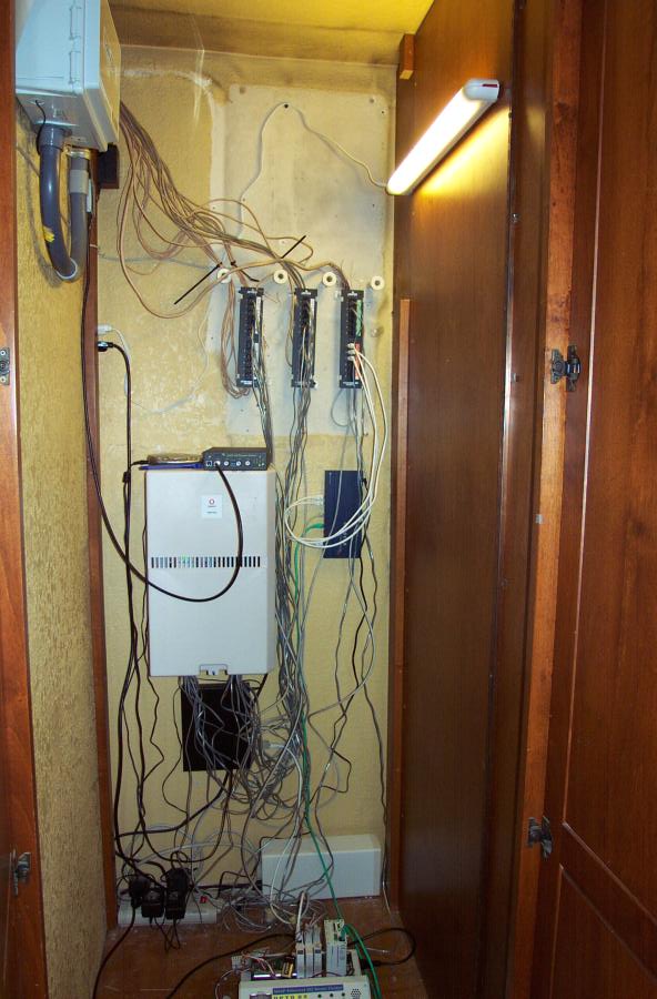
The wire closet is located in the garage. Its primary purpose is to house the phone system, but it also contains a number of additional devices used by the network. |
|
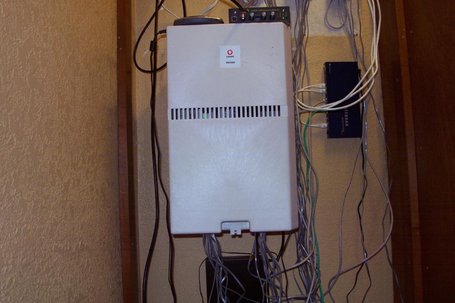
The phone system is a Lucent Partner ACS 3.0 PBX. It supports 8 outside lines and 16 extensions in its current configuration. It also provides voice mail. Most rooms of the house have phones that are connected to this system. The doorbell/doorphone is also connected here, allowing people inside the house to use any extension to talk to anyone who rings the doorbell. |
|
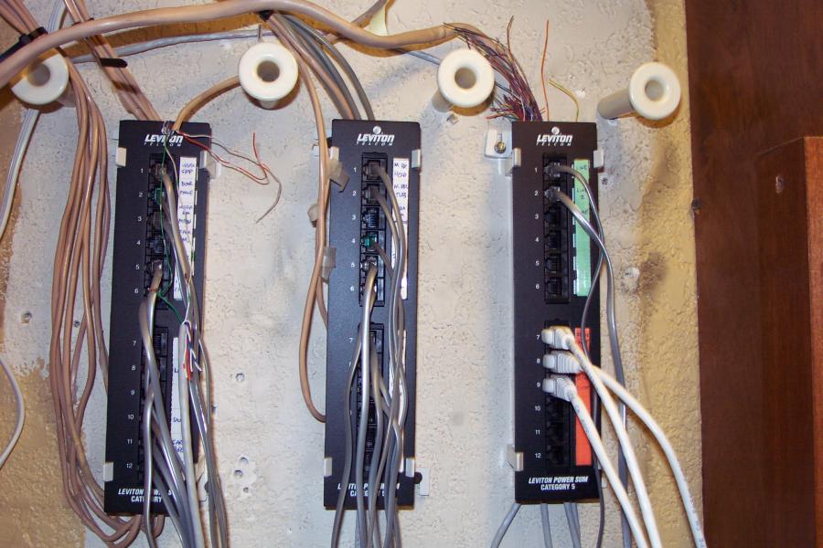
These patch panels help organize the wires that come into the closet from all over the house. The left and middle patch panels are for the extension phones. The top part of the right panel is for outside phone lines, and the bottom part is for various Ethernet connections. |
|
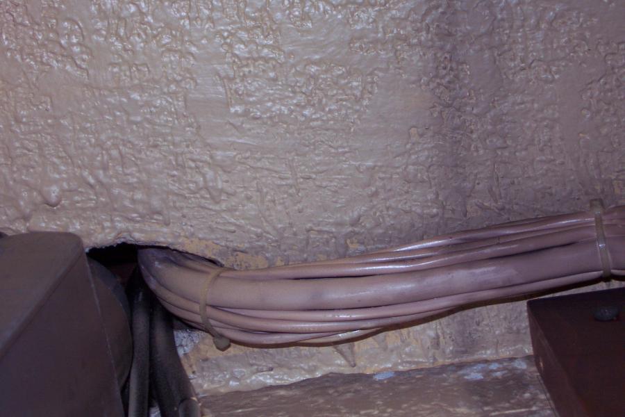
This is how the phone cables for the various extensions and outside lines enter the wire closet through the ceiling. |
|
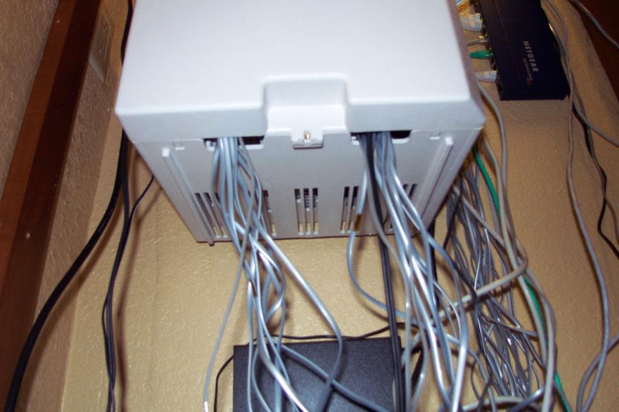
A patch cord for each outside line and extension connects the phone system to the patch panels. This picture shows the patch cords leaving the bottom of the phone system. |
|
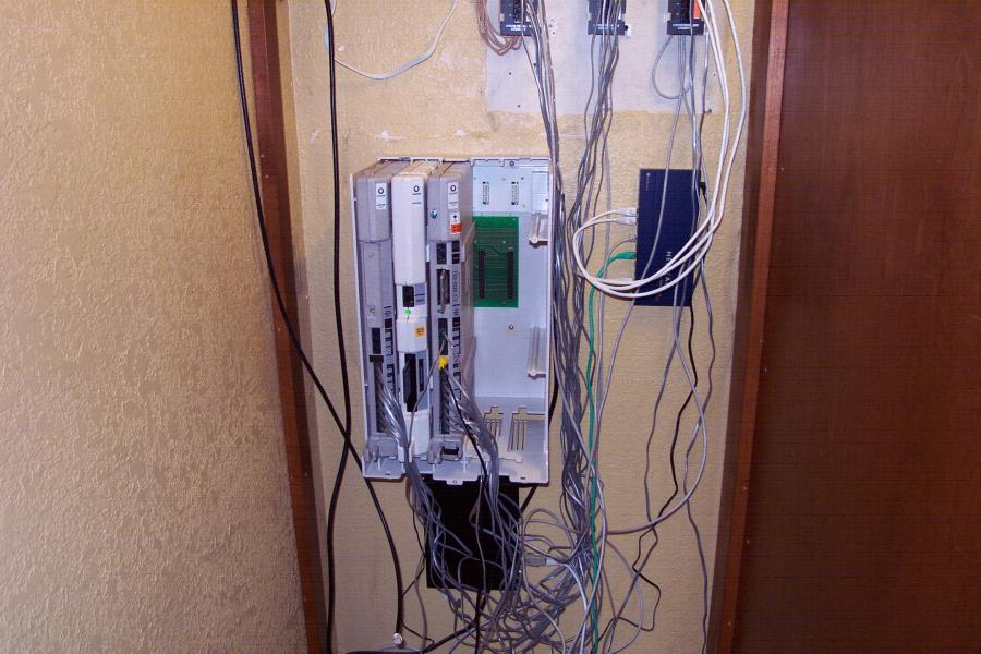
This is the phone system with its outer cover removed. We currently use 3 out of the 5 available carrier slots for components. The components on the left and right support the outside lines and extensions, and the middle component provides voice mail. |
|
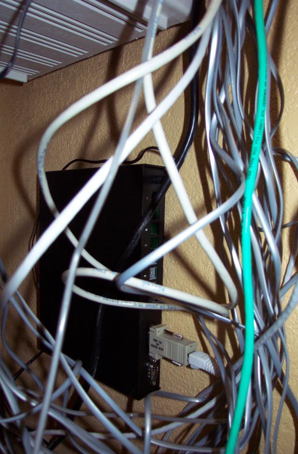
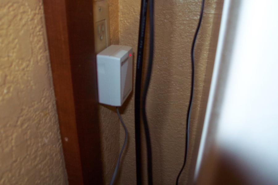
The black box shown here below the phone system is a caller ID identifier built by YES Telecom. It monitors the outside phone lines for caller ID information and sends it over a serial line to our EthernetIO controller (discussed below). This gives any computer on the network here the ability to access caller ID information. We use that capability to keep an HTML log of calls received, as well as display pop-up windows on workstations whenever a call is received. |
|
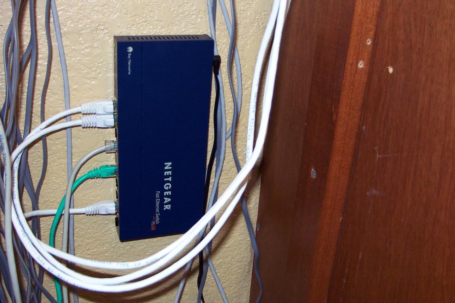
This Netgear 10/100 Ethernet switch is the most critical switch in the house. It ties together the T1 router in the demarcation area with the office network (via the patch panel), the server rack (via the patch panel), and the Ethernet devices in this closet. |
|
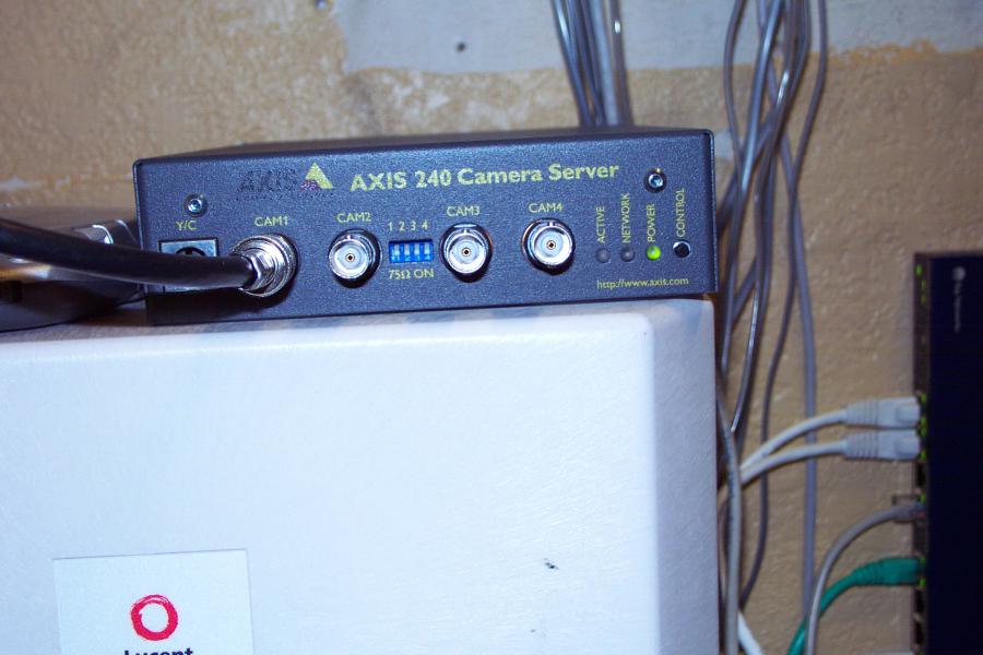
Another Ethernet device in the wire closet is the AXIS 240 Camera Server. This box makes the output of up to 4 cameras available to all of the computers on the network. We currently have only a single camera connected, which is aimed at the front gate. You can load the latest snapshot from the camera server by clicking here. |
|
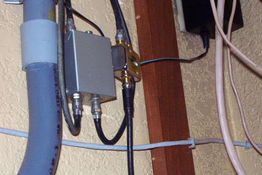
The signal from the security camera makes its way to the camera server through the coaxial cable shown here. |
|
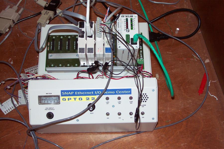
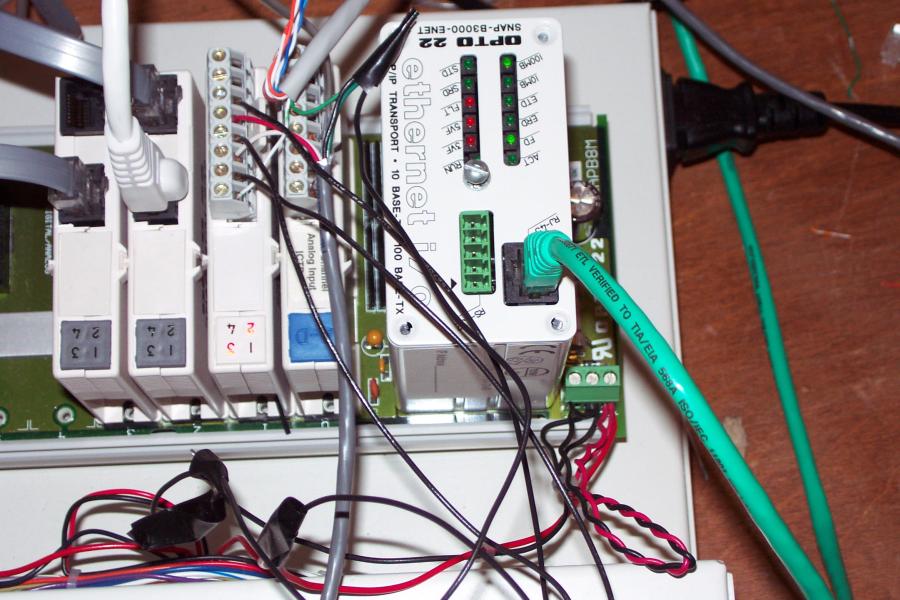
The Opto 22 EthernetIO controller is a modular device that allows you to control various devices connected to it by sending commands and asking for data via the Ethernet. It consists of a "brain" module (on the right side) that is actually a miniature web server, along with multiple I/O modules plugged in on the left side. |
|
Moving from left to right, the first two modules shown are RS-232 serial modules that each provide two general-use serial ports. |
|
This two-way X10 powerline interface allows the Opto22 to control (and get the status of) lights within the house that are connected to X10 receiver modules. These modules work by sending signals, such as to turn a lamp on or off, through the normal power cables in the house. |